Perko Battery Switch Installation Instructions
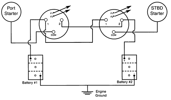
Perko Inc Help Guides Wiring A Perko Battery Switch
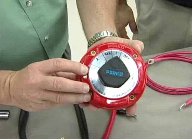
Perko Inc Ship Shape Tv Video Gallery Battery Switches 2

Perko Battery Switch Wiring Boat Wiring Boat Battery Pontoon Boat
Installing A Perko Dual Battery Switch Help The Hull Truth Boating And Fishing Forum
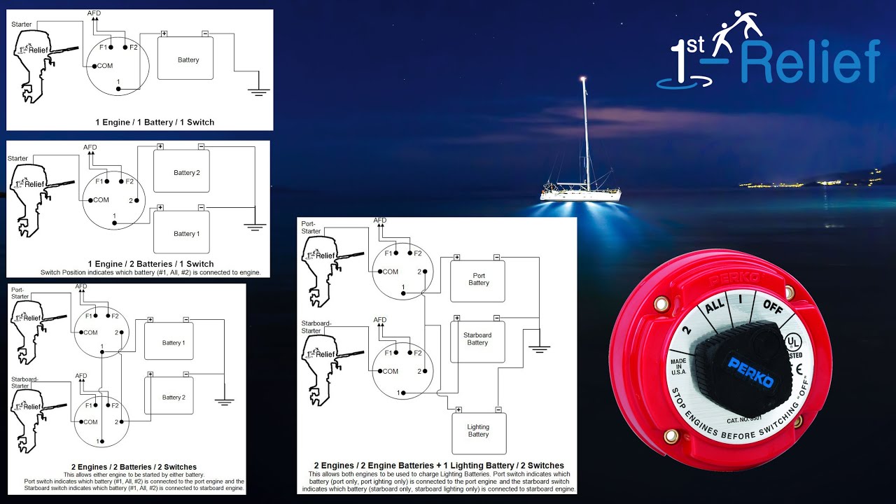
1st Relief Zeigt Die Installation Eines Batterieschalters Support Perko Und Ship Shape Tv Youtube
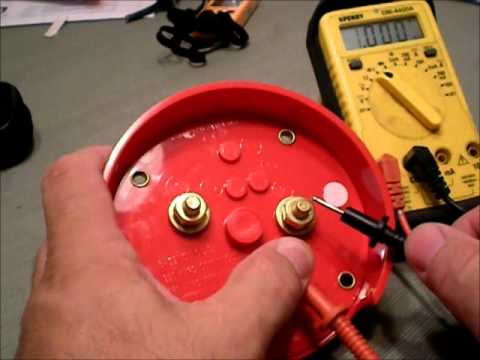
How To Use A Battey Switch How To Hook It Up Youtube

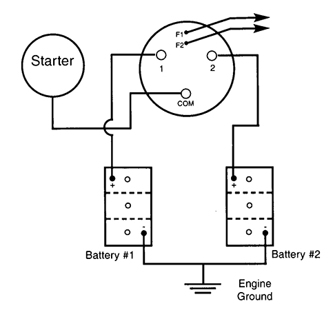
250 amperes continuous 360 intermittent.
Perko battery switch installation instructions.
Guest Dual Battery Switch Wiring Diagram Logic Diagram In Project Management Begeboy Wiring Diagram Source

Scout Com Front Page Boat Wiring Boat Battery Boat

Perko Battery Selector Switches 8501dp Boat Battery Rv Battery

Perko Medium Duty Main Battery Disconnect Switch W Key Lock Key Lock Key Maine

How To Install A Marine Dual Battery Setup For Your Boat Dual Battery Setup Boat Boat Stuff

Diagram Diagramtemplate Diagramsample Check More At Https Servisi Co Wiring Diagram For 3 Phase Ac Motor Electricidad Industrial Electricidad

Pin On Rhodes Electronics Your Friendly Source For Marine Electronics

Best Of Wiring Diagram For Light Bar To High Beam Diagrams Digramssample Diagramimages Wiringdiagramsample Wiringdiagram Check More At Https Bar Lighting
Blue Sea 9002e E Series Battery Switch Selector W Alternator Field Disconnect 9002e Marine Batteries Circuit Alternator

Pin En Electronics Projects

Seasense Led Switch Panel 6 Gang With Breaker And Rubber Boots Cabin Lighting Rubber Boots

Perko Plug In Light Base Rectangular 1059p00dp Chrome Plating Navigation Lights Diy Boat

Home Improvement Circuit Electric Boat

Scout Com Front Page Boat Wiring Boat Battery Boat

Promariner Battery Isolator 2 Alternator 3 Battery 130 Amp Boat Parts For Less Alternator Battery Consumer Electronics

7622manual Control Yescoil Voltage 12vfeatures Manual Control Switch Provides An Added Level Of Safety Allowing Control W Relay Heavy Duty

Blue Sea 2103 Powerpost Plus Cable Connector 3 8 Stud Powerpost Plus Cable Connector 3 8 Studpart 2103 150 Ampere Bus Allows Small Wir Blue Sea Connector

Seasense Led Switch Panel 6 Gang With Breaker And Rubber Boots Cabin Lighting Rubber Boots
Https Encrypted Tbn0 Gstatic Com Images Q Tbn 3aand9gct1fvgpwwe4hhyy Lqenplgivrv0swrt0prhhszzkzxyh66yyk2 Usqp Cau

Red White Switchable Led For Dome Lights Un Dome 15 Rww Dome Lighting Lights Led Boat Lights

Bep 701s Mini Battery Selector Switch Four Position 225 Amps Continuous Bep Marine 701s Bep701s The 701 S Is The Most Compac Boat Battery Switches Battery

Blue Sea 7650 Add A Battery By Blue Sea 125 95 Add A Battery7650the 7650 Add A Battery Simplifies Switching And Autom Electronic Cables Battery Bank Circuit

Promaster Diy Camper Van Conversion Electrical Casa Rodante Proyectos Casas

Blue Sea 3003 Hd Series Battery Switch Selector W Alternator Field Disconnect Alternator Blue Sea Switch
Source : pinterest.com
